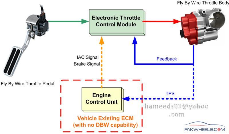
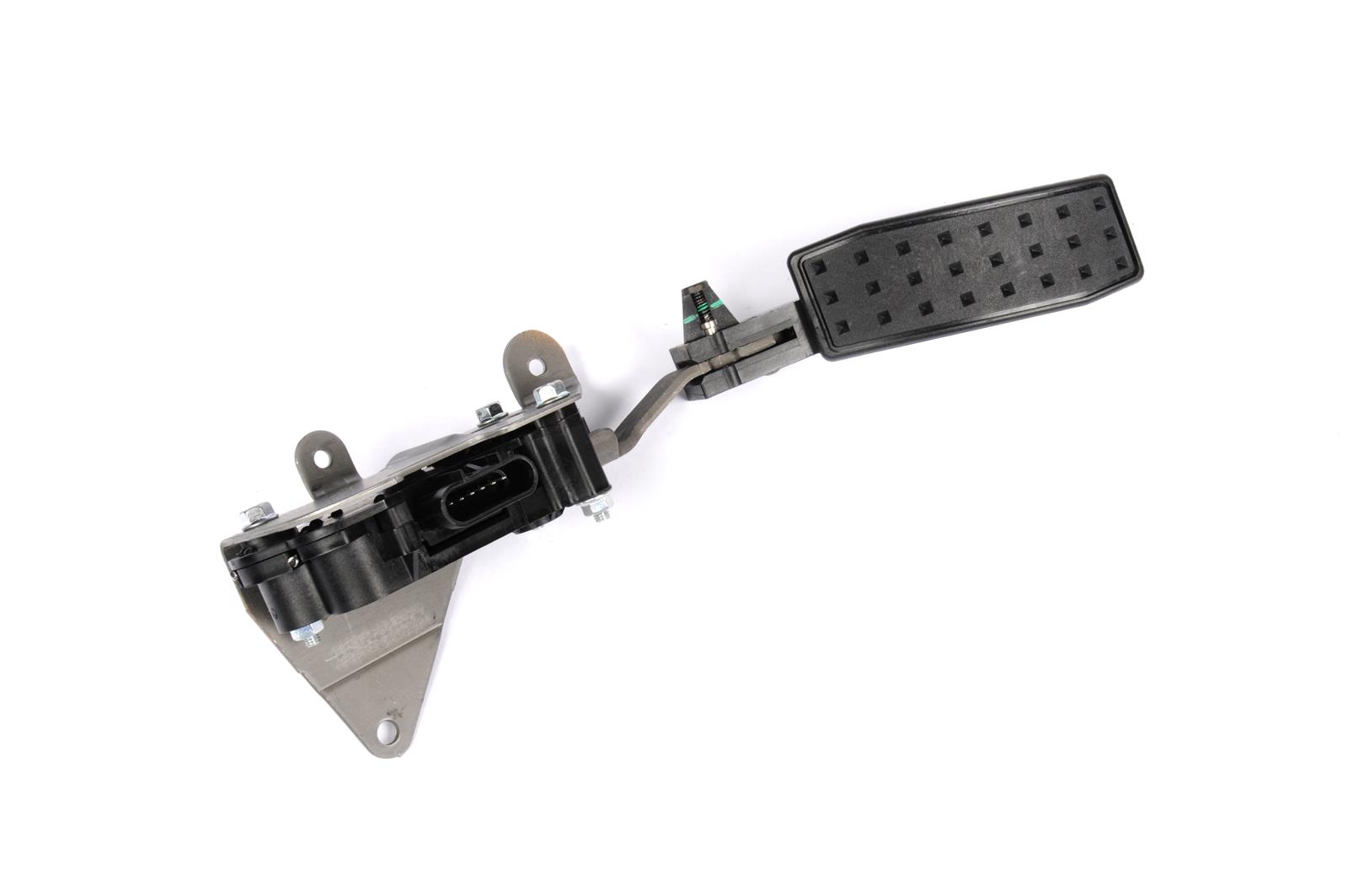
The first programmable electronic throttle pedal (Drive-By-Wire) for the automotive aftermarket Programmable Non-Contact (Solid State) hall effect sensor for most GM, Ford & Mopar applications Splined pedal arm for versatile mounting.
- Many car makers including GM started installing fly by wire electronic throttle bodies. In those vehicles, the “gas” pedal isn’t connected to the throttle body by a cable. The pedal simply provides an electronic signal, telling the throttle body how much acceleration you’re requesting.
- Lokar's Billet Drive-By-Wire Electronic Throttle Control Pedal assembly is pre-programmed at the factory for over 1400 specific OEM and Aftermarket EFI applications including Crate Engines. Included with the Lokar Electronic Throttle Control is an application specific pedal wiring harness that works in conjunction with the OEM or Aftermarket.
- PedalMAX is easy to install and provides a HUGE improvment in throttle performance. It plugs in-line between the vehicle's pedal position sensor and vehicle harness. A control knob is included to adjust your performance 'on-the-fly'. PedalMAX is fully water-proof and utilizes OEM quality connectors. What makes PedalMAX so great?
‘Fly-by-wire’ systems are being used in a lot of cars and pickups on the road today and one of the most common ‘Fly-by-Wire’ systems in use is the one that graces most of the newer GM pickups: the Electronic Throttle Body.
Everything you read about these systems indicate that they are the best thing to ever happen to automobiles. One of the statements that really makes me laugh is this one: “The ETC delivers outstanding throttle response and greater reliability than a mechanical connection”.
The problems I've had with a throttle cable are so few and so far inbetween that I don't recall when was the last time I replaced one.... When was the last time you replaced a throttle cable?
OK, enough of my ranting, in this article, I'll focus on the circuits of the Electronic Throttle Body and how to perform some basic tests on it. You may also be interested in the following tutorials:
- P0120 TP Sensor 1 Circuit Malfunction (With Electronic Throttle Body).
- P0220 TP Sensor 2 Circuit Malfunction (With Electronic Throttle Body).
Puedes encontrar este tutorial en Español aquí: Lo Esencial del Cuerpo del Acelerador Electrónico (GM 5.3L, 6.0L) (en: autotecnico-online.com).
Circuit Descriptions Of The GM Electronic Throttle Body
There are three major components of the GM Electronic Throttle Body and they are:
- Throttle body.
- Throttle Actuator Control (TAC) module.
- And Accelerator Pedal Assembly.
In this section, we'll focus on the Electronic Throttle Body. As you have probably already observed, there are 8 wires sticking out of the Electronic Throttle Body.
When looking down at the Electronic Throttle Body's connector, the top row (from left to right) has 4 wires which are labeled from A to D (see photo).
The second row (bottom row) from left to right, the wires are labeled E to H (see photo).
Gm Fly By Wire Gas Pedal
and here are their specific descriptions:
Gm Fly By Wire Gas Pedal Throttle Body Sensor
- A: (Yellow wire) TAC Motor Control -1.
- B: (Black with White stripe wire) Low Reference... Sensor Ground.
- C: (Brown wire) TAC Motor Control -2.
- D: (Black) Low Reference... Sensor Ground.
- E: (Light Blue with Black wire) 5 Volt Reference.
- F: (Purple) TP Sensor 2 Signal.
- G: (Dark Green) TP Sensor 1 Signal.
- H: (Grey) 5 Volt Reference.
Let's turn the page and find out how the throttle body works in this system...
All modern GM engines (LSx’s, Vortec’s, Ecotec’s, etc.) use the so called “drive by wire” or “fly by wire” throttle bodies. Long gone are the days of actuating the throttle butterfly by mechanical means – ie, a cable – from the accelerator pedal to the throttle body. Instead, the throttle butterfly is now controlled by a servo motor actuated by inputs from an electronic accelerator pedal attached to the ECM. If you Google any of these terms, you will get plenty of info on how it works so I won’t go into the details. This hangs up a lot of folks doing conversions and they end up using a throttle body with a cable. We did not want to go that route. What I do want to show here is how we solved some of these problems on bowtie6 while still retaining all the electronics.
The following pictures show what the throttle body looks like. Since we are running a completely different intake manifold from the Solstice, the throttle body is bolted on a special flange on the new intake. We could have used the plastic intake, but that would have been a major hassle with the steering mechanism. In front of all this is flexible rubber tubing recycled from the Solstice. The silver tube midways is the special housing for the MAF sensor and ahead of that (hidden by the radiator and ahead of the rubber bend tubing) is a K&N air filter. On bowtie6, the air filter sits ahead of the radiator, right behind the factory grille allowing the coldest air to be pulled in. However, this all comes at a price: the MAF must be re-calibrated because of all the bends in the airflow.
This is what the whole shebang looks like…
Here is a closeup of the throttle body…
This is the stock throttle body as found in the Pontiac Solstice/Saturn Sky. The grey plastic cover hides the stepper motor and the rest of the mechanism that opens and closes the butterfly activated by the ECM. Here is another picture from the back of the throttle body showing the connector plug with the wires coming from the ECM.

Finally, here is what the inside of the throttle body looks like. I reckon this all could eventually be fully polished, however I have doubts on how great that idea would be and whether there would be any benefit in that. At any rate, it is what it is…
As you can see, there is no cable. This is all controlled electronically. Right before ignition, the engine does a “test” of the throttle body and yes, there is a split second delay. If you pay attention, one can actually hear the stepper motor in the throttle body opening the butterfly to WOT and then back to the closed position. Then ignition occurs.
If you are looking at all this and wondering where the traditional Idle Air Motor is then you are correct: it is not here. Idle is handled by the ECM and TPS. From there, the butterfly opens to control idle.

Controlling all this requires the special matching throttle pedal. Here is where things get interesting. There are quite a few versions of these throttle pedals. For example, Vortec engines have a certain version, GTO has another and Vette’s have yet another. Along with that, some are all plastic, others are plastic with metal arms, some have 6 wires and some have 8 wires. In our case, we used a throttle pedal used in the 2.4 Ecotec powered HHR. The advantage of this pedal is that the actuator arm is metal, and thus can be cut and shaped to fit the location where it is mounted in. This is what the one in bowtie6 looks like:
Sorry for the boring gray background (this is a sound insulating material glued to the Dynamat Extreme prepared body) but thought it be best to take this picture before I install the black carpet. Otherwise we won’t be able to tell squat of what this looks like. Some things to keep in mind about what you see above:
Gas Pedal Lyrics
- The pedal is still a little “crude”, if you will. This is version 1.0 of the pedal. So far even though it works perfectly there is some issue with the exact angle of the plastic pedal itself. As you can see it is still a bit too straight. I am planning to fine tune it by angling it a bit – the top needs to be brought down a little and the bottom needs to come up. I just need to make up my mind on how far to make the angle. It is also a bit long. As you can see the top is rounded somewhat. I need to make the bottom rounded as well.
- The “travel” takes some getting used to. This is a small compromise but this has to be retained because this is the way the ECM is expecting the signal to be sent. If you look closely, there is a plug at the top with some wires going into a housing. This is where the potentiometer that translates pedal movement into a signal resides. This is what tells the ECM what throttle angle is being requested.
- Looking at the picture above would lead you to believe the metal “arm” hits the red body of the car at the top, right? Nope. The travel is not great at all and the arm does not touch the body at WOT. I also own a 2.4 Ecotec powered HHR and the throttle travel there is equally short. However, believe me – this is not a problem at all when driving the car. The throttle has the same “look and feel” as a mechanical system does. It just takes a little getting used to.
For those of you considering an Ecotec conversion, this is going to be a very important issue to figure out. Like I said before, there are many different varieties of thottle pedals. I have read where there are some that are actually meant for the V8’s. Once you settle on the correct pedal to use, placement will require some adjustments. Mine is close but not quite 100% perfect yet.
There is yet another alternative and that is to use a Lokar fly-by-wire system. I think these were introduced at SEMA earlier this year. I have done some reading about them but I have not seen one in person and have no idea how helpful it would be. On the downside too is the price – they are quite price. The stock GM stuff can be had for a few bucks at your junkyard or from auction on eBay.